Wednesday, July 30, 2014

The Connected Cockpit

The internet of things (IoT) is kind of the current discussion in many publications. The idea behind the internet of things is that everything will be connected to the internet, allowing monitoring and control of those things. As things are going, it is still too expensive to connect everything to the internet, and there many implications of connecting everything to the internet.


Many aircraft are getting WiFi in the cabin, people think the next step is putting an iPad in the cockpit, and connecting to the cabin WiFi and that should do it. Get all the flight plans, updates, weather and other data from headquarters we are all done. The trouble is, and was pointed out in the first post of this blog, there are security thoughts that need to be considered.

On transport aircraft, most of the cockpit is connected. Well connected, in that the FMS talks to the airopilot, and the EFIS may talk to the ACARS system, and the radios share a common bus. The trouble is, the cockpit is not talking IP, so it isn't easy to connect it to the WiFi, and it probably isn't a good idea.

In your GA business jet, it might be OK to connect the cabin to the cockpit. The people in the aircraft are usually well vetted, and may actually own it. They have a serious reason to be riding in the aircraft to the destination. Smaller aircraft may not have the means to get WiFi to the ground, but WiFi or other Ethernet connections could actually be done allowing the GPS to talk to the ADS-B transciever, and the MFD in the panel.

Allowing the cabin WiFi be connected to the cockpit of a part 121 transport aircraft is probably a bad idea. Probably the biggest problem would be if the aircraft were in a place with weak connection to the ground, and bandwidth was limited, who would get priority, the passenger watching Netflix or the cockpit needing a new route around some weather. The marketing department might argue the passengers, but flight operations department might argue the cockpit should have priority.

The other reason connecting the cockpit to the cabin using WiFi is a bad idea would be straight up security. There would be 100 people in the back bored wondering what is going on in the flight. It may be a curiosity for some, or a goal for others, they may just want to look at things, and manage to get access to say the current flight plan, in the FMS, and accidentally adjust it. Sure there could be firewalls and whitelists and other techniques to keep only the cockpit in the cockpit network, but there are ways for others to get in.

Having a separate cockpit connection to the ground is probably the right answer to the security question. having an isolated cockpit will make it harder to keep the cabin people out of the cockpit network.  It will be important to consider all the connections to the cockpit, and how secure they may be. If there is only an unsecured connection to the cockpit, then the cabin can probably still get to it through some ground station. Worse, if the cockpit doesn't have a secure connection to the ground, now there may be thousands of bored people trying to see what is going on in the aircraft.

Security has to be the first thought when building cockpit connected interfaces. Security through obscurity isn't real security, so proprietary standards won't be a long term solution. Bored people look at proprietary standards as a new challenge, and eventually they get figured out. Using industry best practices will be the only way to insure interoperability along with proper security.

It may be that the aircraft cockpits are only connected using one vendor (IE ARINC as things are today), where they provide an isolated network that only they can get to the aircraft. The messages will have to pass though a filter, and have proper originator white lists. All messages would be encrypted such that only known originators and destinations can see and use the messages. Certainly ARINC can't let Southwest Airlines read Delta Airlines messages, as well as some random person on the ground should not be able to sent messages to any aircraft.

It will take a bit of time for things to shake out, but eventually the cockpits will be connected.

Saturday, July 19, 2014

Thoughts On Cockpit Electronics

Recently I was playing an EFB type app. I think I've mentioned it on my other blog, and I am mostly happy with Avare. This app will allow weather downloads, and is a moving map and can display charts of most types (Sectional, WAC, IFR Low and High, etc). It has built in AF/D, can display approach plates, and topographical data.


While using it, I was surprised by a few things, and it occured to me you cannot just buy the latest technology and go out and blindly rely on it. You really need to know how it works, and test it out for a while.

I flew with the Avare app on a Samsung Note 10.1, and found a few anomalies with the system, and I am sure other apps and tablets have similar anomalies. I was testing the app out while riding in the back of a 737, and the GPS was mostly unusable back there. On takeoff it seemed to work well and I could see the acceleration down the runway, and the climbout was displaying nice. But about the first turn, and suddenly the GPS wasn't working at all. No speed, no heading, nothing. Then it was intermittent the rest of the flight.

Avare, like most moving map applications can take another GPS source as the input. There are several manufacturers that offer standalone GPS source devices (IE Garmin). Avare even offers an app you can run on another device (IE phone) to use that GPS source to feed the application. On my next flight, I ran the external app on my phone, and was feeding Avare with the GPS output from my phone. The phone was in my pocket, and I had a window seat, so it worked almost 100% of the flight.

Since the my phone GPS wasn't 100% reliable, it was a good test. I've mentioned Kalman filters in other posts, I wanted to see if this app had any coast mode, where the application would predict the location based on flight plan and last few samples, but it didn't. When the GPS signal was lost, the airplane on the magenta line would point straight north, and stop updating. This by itself was a good thing to know, since GPS isn't 100% reliable in any situation (see the RAIM predication post), and it is good to know what indication is out there when the GPS signal isn't there. When the GPS data was available again, the airplane symbol oriented itself to the flight path the aircraft was following.

Another test I found out about, the hard way, was the chart updating. The charts are generally current for a period of time, some are 28-56 days (IE approach plates) and others up to about 6 months  (IE sectionals). Some of my charts were out of date. The app has a nice feature allowing bulk downloads of charts, but not while out of WiFi range. Most charts are big files, that take a while to download. Even a 737 with WiFi on board isn't the best place to bulk download charts, since most of the flight may have taken place by the time it updates everything (depending on how many plates are out of date). It is best to do the bulk update the day before the trip, to allow time to make sure everything downloads, and the WiFi at the hotel is reliable, the FAA didn't change anything  and everything else works.

Another problem I found, the 10.1 inch tablet might be too big for a cockpit. If I was flying an A380, it might be fine, but even in the seat in the back of the plane, occasionally it got in the way. It would be nice to try an 8 inch tablet next time. The 10.1 inch tablet is about an inch wider than my knee board on all sides. It might be nice to find a knee board adapter for a tablet. Knowing were it is, and what happens when accidentally touched might be a good thing to know. I tapped the screen multiple times on the flight, and sometimes the screen would go off center, I would have to punch the button to set the center again.

Entering a flight plan on the flight was frustrating at best. For the flights I was on, I could look at the route on flightaware.com, and see what waypoints to enter. I was on a flight from DAL to MSP, that stopped in STL. I needed to enter two separate flight plans, which would have worked much better in the terminal rather than in my seat. Then when I got done, I needed to activate the correct one. At first I had forgotten activate the first plan I entered, so the magenta line didn't show up. The Distance Next and Estimated Time Next were updating as if we were flying a single leg flight.

When we began our approach to the middle airport, I thought I could click on the approach plate, and the app would plot the current position on the plate. It didn't, which made sense after I thought about it, since the approach plates aren't always drawn to scale nor have consistent references, and SIDS and STARS never are drawn to scale. The app was smart, since it knew where we were, and punching the "plate" button brought up the correct airport diagram, and I could select the approach, SID or STAR I wanted to use.  A split screen feature might be nice, especially on a STAR.

The weather feature is nice, since it loads most of the standard weather products, (IE METARs, TAFs, PIREPS) for areas along the route. It wouldn't make sense to get a METAR for Chicago if I am going from Dallas to St Louis, and this seems to do a good job. The weather isn't updated if there is no data connection. Some apps will work with a FIS-B receiver, but even those messages may not be as timely as pilots need in a dynamic system. Talking with Flight Service is still the best way in busy weather systems.

I really enjoyed using the app. I can see it being a tool to rely on. I can also see I need to work with it a bit more, and read the manual. Other similar apps are probably just as good, and will need careful integration into any flying procedures. The FAA doesn't allow using handheld GPS devices for primary navigation in IFR conditions, but for VFR, there should be nothing wrong with using this for navigation.

What do you use?


Monday, June 16, 2014

RAIM and GPS


Wow, I can't believe I haven't written this post yet. I have mentioned RAIM in other posts, but I haven't explicitly explained RAIM. RAIM used to mean Redundant Autonomous Integrity Monitoring it was a technology built into many GPS receivers. TSO-C129 required GPS receivers to have RAIM built in. It would monitor the quality of the GPS signal, and if things were bad enough, the RAIM system would alert the pilot that things aren't working.


If you go back to the NextGen post I did a little more than a year ago, I mentioned RAIM, and the FAA's RAIM prediction tool: http://www.raimprediction.net this tool will predict places in the CONUS where the RAIM alert will go off in the future.

The GPS signal is just telling you what the time was when the satellite sent the signal. The satellites also send location information along with the time. The almanac is the location of all the satellites in the constellation. Knowing the time the satellite sent it's signal, and knowing where the satellite was when the signal was sent, the GPS receivers are able to triangulate (sphere-iate?) their location.

The satellite time message is sent every few minutes, and is susceptible to all kinds of problems. The message may bounce off buildings, mountains or other vehicles causing a wrong distance to be calculated. Other times the satellites will be down for maintenance, and testing, so it won't be available for measurements. Knowing the current status of the constellation is critical to make a valid prediction. Knowing local terrain will help make predictions more accurate.

With GPS Helpers, RAIM prediction is not needed. Using satellite or ground based augmentation systems (IE WAAS, LAAS) the number of satellites isn't as critical. Knowing the WAAS system health is required, and the FAA will issue NOTAMs if the WAAS system isn't up to snuff.

As you can see RAIM has its use, and can make older GPSs more usable.

Saturday, June 7, 2014

FAA and UAS

The FAA has a huge challenge, they need to get it right the first time. If they screw it up, and a UAS and a passenger aircraft have an issue, where people get hurt, there will be no more UAS allowed! Of course, the UAS industries are clamoring for changes now. Claims of huge employment are dubious, since it will only transition pilots and maintenance from manned aircraft to unmanned (peopled, what is the right non-gender word).

If people think everything under 400ft (1000ft, 2000ft, whatever) should be unregulated, what happens when a traffic accident occurs, and a medical helicopter has to thread it’s way through 5 local TV stations with their quad copters filming the carnage? What are the rules around an airport? The rules have to at least match the controlled/uncontrolled/class A/B/C/D rules that exist for manned aircraft. Rules need to be established, such that assistance cannot be delayed.

Quad copters and other UAS devices are easy to fly when the weather is nice and there is little wind and turbulence. What happens when there is turbulence, or dust or other weather that makes visual queues, and control difficult. How about a slightly damaged older device that isn’t well maintained, and the operator is inexperienced. The innocent people on the sidewalk should expect a reasonable amount of safety near these devices.

Many of the smaller quad-copters are only controllable indoors, and some of the larger ones are controllable in moderate winds. Larger UAS systems are less prone to weather, but are more dangerous to people around them. What happens when an editor or producer is clamoring for a news story on a stormy day? What is the poor UAS operator to do, fly anyway? The operators will be glad to have an FAA regulation that says it isn't safe, so they won't have to stress about it.

There will need to be right of way rules. Right of way rules make knowing what to expect from the other aircraft. It is all great to have see and avoid, but what is the understood direction to avoid things? Most R/C fliers operate with one aircraft in the pattern at a time, so they don't have too many right of way issues. Much of this will be new territory to UAS operators.

For commercial UAS operators, there will need to be maintenance programs designed. Basic maintenance will need to be regulated to insure the craft is controllable, as well as structurally sound. Having a UAS disassemble in flight will make the situation for the operator inconvenient. Inspections, and preventative maintenance programs will have to be defined. 

There will be all kinds of other regulations that most people haven’t considered.
Pilot licensing being one. If a UAS is to be operated in the same airspace as a manned system, the operator MUST know the same rules as the manned aircraft, at least to know what everyone will expect in right of way situations. 

The FAA could mess all this up and not regulate it properly, and people will get hurt. The FAA is already granting exceptions for certain groups, but this sets a bad precedence. They could rush, or some manufacturer could lobby congress to get the FAA out of the way, and people would get hurt. If a UAS took down a 737 you will see congress act!

Everyone needs to be a little more patient, and let the process work it’s way out.

Wednesday, April 30, 2014

Trig You Thought You'd Never Need

Sure, most people took trigonometry in high school, or college, and wondered when it would be useful. It was handy in calculus, if that course was also taken, but then it becomes one of those interesting why did I ever learn it kind of things.

Computer graphics is the reason to review it. Hopefully this will be a gentle reminder, and something that can be applied right away. There shouldn't be anything scary here, and it should be a reminder, and not something that requires hours of complex math to have it make any sense. This will apply to computer graphics, and will show shortcuts in ways that make sense.

I will assume that there is some facility that can be used to draw the computer graphics with. Even using a spreadsheet, some of these concepts can be figured and displayed. Most spreadsheets will allow Sine and Cosine calculations and a table of Y and X values to be plotted. Using that concept, most of these ideas can be visualized.

Starting with those two functions that didn't seem to have any relation to anything, Sine and Cosine. The Sine button returns some number when entered in a calculator. That number is kind of a percentage of the way around the circumference of a circle, or at least a quarter of one, since it goes negative about half way, and the numbers repeat on the odd quarters. Cosine is similar to the Sine, but it repeats in the middle two quarters, and starts at 1 instead of 0.

The diagram above shows the relationship to the circle, angles and the functions. Notice that the X position of the outer end of the line is the Cosine value, and the Y position of that same end is the Sine value. The X and Y value of the other end of the line will be the center of the circle or 0,0. This is called the "unit circle" since the radius of the circle is 1. To make the circle larger or smaller, just multiply the returned Sine and Cosine value by the radius desired.

Angles can be measured in degrees or radians. Most people are comfortable using degrees, since they tend to be whole numbers, starting with 0 and going to 360. Computers work better in radians, which is values between 0 and 2*pi, but they also come with conversion capabilities. In Java, the Math class library contains toDegrees and toRadians static methods. Pass a degree value to the toRadians function, and the computer will return the equivalent angle in radians.

An Application

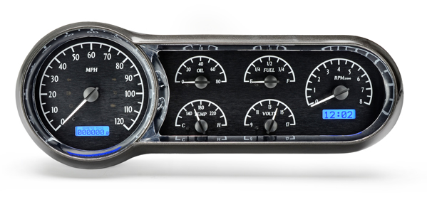
Most instrument panels in modern aircraft are computer screens. The Engine Instrument Systm (EIS) display in the aircraft will draw the values of the engine in round gauge representations, like the old analog instruments. Applying the Sine and Cosine thoughts above, the values can be easily displayed in a nice analog looking gauge.


The first thing to consider when drawing the gauge is how big around the gauge will be. The one unit circle will allow scaling by multiplying by the desired radius. A simple gauge might be 100 pixels in diameter, and on a 100 pixel per inch screen, that will be about about a 1 inch circle display.

Most gauges don't go all the way around. Many only go 270 degrees, and some only go 90 or 180 degrees. Choosing how far around the gauge goes will be key to plotting accurate instruments. The instrument may not be oriented at 90 or 180 degrees, some displays will show gauges starting at 45 degrees.


The tachometer and speedometer gauges in the above cluster are 270 degree gauges, starting at 45 degrees (or really 235 degrees). The other smaller instruments only go 180 degrees. Thinking of the line as the pointer on the gauge, the place where the end will be drawn will be a fraction of that number of degrees.

For the time being, ignore the direction of rotation. The animation at the top of the page shows counter clockwise rotation, and that is normal for trigonometry. There is a shortcut to reverse that if desired, and that will be covered later.

To build a speedometer as shown above, with a 270 degree display that goes from 0 MPH to 120 MPH the math is simple ratios. Use the speed to be represented, 60 MPH and divide that by the maximum speed, 120 MPH to get the fraction of the circle that the needle will need to cover. 60/120 = 0.5. Multiply this result by the maximum angle that the speedometer will display, 270 degrees * 0.5 = 135 degrees. So to draw the needle on the speedometer, calculate the Cosine and Sine of 135 degrees to get the X and Y values of the
unit circle, then multiply those values by the radius of the display, and draw a line from the center to the specific position.


Translation

Sine and Cosine maybe is starting to make sense. Then the computer part starts to complicate things. The Sine of 135 degrees is -0.7071, but the screen only goes from 0 to 1000 or so. If a negative value is plotted, it will be plotted off the screen somewhere. Some computers handle that gracefully, while others won't. Either way, the results are not what the users expected. The drawing must be translated to the proper position.

Most drawing planes start with 0,0 in the upper left, where the trig unit circle tends to have the 0,0 position in the center. The actual drawing center needs to be moved down and to the right. To move the circle from the unit scale to the drawing canvas, the coordinates must be added. The origin X and Y position should be changed by the radius of the desired circle. As the picture above shows, the center was moved from (0,0) to (50,50).

The end point must be scaled and translated. To make the end be on the 50 pixel circle, the the -0.7071 should be multiplied by 50 giving about -35 pixels, and the 0.7071 also multiplied by 50 giving about 35 pixels. The (-35, 35) needs to be moved down and to the right. To the right is mostly straightforward, by adding 50 to the -35 the results will be the expected 15 X position. The Y position requires an inversion, because the positive values on the unit graph go up, where the positive values in the drawing canvas go down. The new Y position is mirrored and adjusted 100-Y+50 or 100-85=15. The center has the same Y inversion, but 100 - 0+50 is still 50.

To draw a pointer at 255 degrees, the point on the unit circle will be (-0.2588,-0.9659). To translate that to a 50 pixel radius drawn canvas, again the center will move to 50, 50. The X position will be 50 * -0.2588 = =13, and 50 * -0.9659 = -48. (-13, -48) translated will move it to  (50-13=37, 100-(-48+50)=98).

Maybe translation is harder than the trigonometry?

The speedometer gauge that is shown in the picture above has the 0 speed at 235 degrees, and the needle rotates clockwise. To make that work properly, there will need to be some additional translation. A shortcut to reversing the rotation is to mirror the gauge. Since the gauge is centered about the Y axis, it is easy to mirror the values, by subtracting x value from the width.


 By using the normal sine and cosine calculations, the same Y translations, calculating the X position as above, and subtracting the X value from the width, the rotations will be clockwise.

Rotation

The speedometer above still doesn't start at the horizontal origin. The 0 MPH value is about 45 degrees below the horizontal. Sines and cosines are cyclic functions. Cyclic means that if the rotation continues past 360 degrees, the sine and cosine of next 360 degrees will be the same as the first 360 degrees. The sine and cosine of a negative rotation will be the same as 360 + negative angle.  The sine of -15 degrees is the same as 345 degrees (360 - 15 = 345).

Moving the 0 speed down 45 degrees is just a matter subtracting 45 from the angle calculated for the speed.


The rotation will still use the same ratio of Speed/maxSpeed * sweepAngle, but after that calculation simply subtract the desired rotation. In the above display, the 135 degrees will be changed to 90 degrees (135 - 45 = 90). The sine and cosine will be calculated after the rotation. Don't worry about values less than 45 degree, the cyclic nature of the sine and cosine functions will return the proper values.

More Applications

The above work is good for pointers in a circle display, and can be used for drawing tick marks and placing the numbers in a gauge. For calculating tick marks, consider a line with two radii. There is an inner radius (r1) and an outer radius. The same calculations will be used, but the start of the line will be at the r1 point, and the end will be at r2.


To draw the tick mark at 80 MPH in the above drawing, first calculate the angle, including the rotation:

    Angle = (Speed / maxSpeed * sweepAngle) - rotation
    Angle = (80 / 120 * 270) - 45
    135 = 180 - 45

So this will put the pointer to the left of vertical, but in the X calculation it will be mirrored across the Y axis, and end up in the proper right of the Y axis position. The X and Y are calculated using the Angle found in the previous calculation as explained above:

    X = Width - (cosine(Angle) * radius + Width/2)
    X = 100 - (cosine(135) * 35 + 100/2)
    X = 100 - (-0.7071 * 35 + 50)
    75 = 100 - (-25 + 50)

    Y = Width - (sine(Angle) * radius + Width/2) 
    Y = 100 - (sine(135) * 35 + 100/2)
    Y = 100 - (0.7071 * 35 + 50)
    25 = 100 - 75

The X and Y calculations above are for r1, r2 sould be calculated using the same angle, and change the radius. The tick marks are drawn as a line between r1 and r2 on the canvas. The placement of the numbers near the tick marks can be done as above using another radius.

The above calculations are rounded to integers. Some drawing canvases will take floating point numbers. If the drawing canvas will take floating point numbers, it is best to leave the values in the calculations in the floating point format, so they may be as accurate as long as possible.

To build the other smaller gauges above, the above calculations apply, but the sweep angle changes to 180 degrees, and the max value changes to something appropriate.

To see the application of this work, follow my other Blog.


Tuesday, February 18, 2014

Flight Simulators and Airlines

Did you know that for many pilots, the first time they fly a particular large aircraft, there are paying passengers in the back? Scarey, not really, since those pilots probably have hundreds of hours in simulators. These simulators are big expensive devices, that operate very similar to the real aircraft, and give the pilot almost all the sensations of being in an aircraft.

 The simulators that the airlines use have rules similar to aircraft. 14 CFR part 121 appendix H covers Advanced Simulators. These simulators are typically held in a specially built building. The simulators weigh several tons, and are up on legs (usually 6) that move with hydraulic or electric actuators to give the occupants the feeling of being in flight (or landing). The legs are usually isolated from the rest of the building, both for extra support and to prevent the other parts of the building from feeling the motion.

There are several computers that run these simulators. Some of the computers make the instruments behave like the aircraft in flight, others generate the scenery that the pilots see out the "windows" and other computers generate the motion that give the occupants the feeling that match the instruments and the scenery. These computers are generally quite powerful, to minimize any lag between the pilots inputs and the changes visible and felt. It is especially important to have the motion match the visual, to prevent the occupants from getting any form of motion sickness.

Like anything mechanical, the simulators will break on occasion. The extent of the break will cause the simulator technicians to determine if the simulator meets the FAA requirements. If it can be used, it may have a minimum equipment list deviation (MEL). If the simulator is broken too bad, it may not meet FAA requirements, and will be taken off line until repairs can be made. Any MEL deviation can have a list of operations that cannot be performed, just like a transport aircraft.

Changes to hardware and software are covered by the same FAA 14 CFR 121 appendix H. Basically, what the simulator was built with, is what it must have every day. Occasionally the manufacturer will make major modifications to a particular simulator hardware, but that will be rare. Many simulators are over 10 years old, still running the old hardware from when they were new. Technicians must keep 10 or 15 year old hardware running, and source spares for them. Most simulator manufacturers will choose OEMs who understand that and make every effort to insure the OEMs will have enough spares to keep these expensive devices operating 24x7x365.

The software will get changes on occasion. This is normal, and is less expensive than replacing hardware. The FAA requires review of software for any impact to the performance of the simulator. The software review request must be sent to the FAA at least 21 days before using on the simulator used for training. The software must be test flown, and checked for any performace changes. If the aircraft performance changes (IE due to SB or AD), then it will be mandatory for the simulator to be upgraded to match the change.

As life goes, the FAA also makes changes. Navaids change, runways change, and other facilities change (new terminals, control towers, etc). Most simulator operators have staff of technicians that will keep the simulator data up to date. Every 28 days the FAA publishes new information (AIRAC cycle). The technicians must keep the simulators navaids and routes matching the current charts. Over 10 or 15 years, scenery at airports change, along with many scenery items. The technicians must keep all this information current as well, so the pilots know what to expect when they get to a particular airport.

Operating these simulators can be very expensive. Some estimate that a full motion simulator for a part 121 aircraft can be over $1000/hr. When the technicians time, as well as building costs are factored in, it may be more costly to operate the simulator.

For a new pilot to come into the full motion simulator, they would spend most of their time just getting familiar with the basics. Throttle quadrants and yokes are pretty standard, but it is all the other systems that the new pilot needs to know, and take so long to find. There are other simulators for getting familiar with the basic systems.


The most basic simulator, is the cardboard cockpit, also known as a procedure trainer. This procedure trainer is usually in an office, with some tables covered with cardboard printed with switches and indicators that look like a cockpit. The pilots will use this to set up the "flows".  This allows the pilot to go through each checklist, and know where the switches are and what indicators to look at to verify a particular operation. The pilots can also use the procedure trainer to go through emergency and other off normal operations.

The next simulator will still be called a procedure trainer, but will have operating switches, yoke, throttles and displays, but probably no scenery out the windows. The advanced procedure trainer can be used for flow checks, and also instrument procedures. Many of the same computers are used in the advanced procedure trainer, but will not be as complex, since it is missing the scenery and motion.

The full motion simulator, and the advanced procedure trainer have an extra computer. The instructor console is outside of the cockpit area, and is used to set up various training scenarios. Scenarios can altitude and position settings, allowing pilots to train on specific aspects of a flight. Other settings can include weather, and mechanical issues. 

All simulators require maintenance. There are various people involved in the simulator business. Pilots are well trained before ever stepping foot in the cockpit of a real aircraft.


Saturday, February 15, 2014

How To Design an Autopilot

An autopilot is a very complex bit of machinery. Ever think about all the stuff it needs to know and how it does it so well? As a pilot, you were taught that you start a turn before you get to a waypoint, so you don't overshoot. As a computer, how do you know to start a turn before, and how much before?

The FAA has an amazing document, AC 8260.58. I recommend getting the whole PDF, and opening it in a true Adobe reader because this document is interactive, and it is large. This document is full of very well explained math. There are tons of definitions and discussions in here, PLUS there are sample calculators right in the document.Depending on the age of your Adobe reader, you might get some weird document navigation indications.

The document is really about how PBN procedures are designed. PBN procedures assume the aircraft will have an autopilot, so it is interesting to see how the procedures are designed for the limitations of the autopilot.

The drawings in the document are amazing. Look in volume 5 page 9 figures 2-4A and 2-4B, to see how turn errors can be calculated using the radius of the required navigation performance, and bisector lines, and the arc that intersects the edges. The page before (page 4) explains step by step how to make the calculation.

The document is full of acronyms, but they are all explained in volume1 chapter 3. Not all the acronyms are what you might think or are used to in other contexts. In this document CG is "Climb Gradient" not "center of gravity", ATT is "Along Track Tolerance" not that big phone company, etc. It is best to have that chapter book marked to allow you to check back.

The book outlines other tolerances as well. Some of the measurements are metric, while others are nautical miles, and the conversions are part of the calculators in the document. Many of the intermediate values need to be kept in 15 significant digits, and stored in 64bits, with no rounding of intermediate results. There are other common standards that this document relies on, including GPS units calculate the diameter and shape of the earth based on WGS-84 standard.

Much of what is in the document is code that could be copied right into some programs. What code isn't there, is mostly easy to figure out, and could be part of a separate function or method. 

There is a good review of many basic algorithms, including intersections of two arcs, locating a point relative to a locus, and calculating arc length, or sub-arc lengths. 8260.58 might be a good workbook for some advanced STEM type program.

With this reference, building an autopilot should be less searching, and easy implementing.


Tuesday, February 11, 2014

Resources

Wow, the internet is full of documentation. If you go back to the roots of the world wide web, people like Tim Berners-Lee and before him even Ted Nelson with project Xanadu (and go back to the Manhattan project with Vannever Bush it isn't a new idea at all) the idea was to share information. Learning material, instructions and books could all be connected.

This blog is all about sharing and linking. This is information I have gathered either professionally, or just as part of learning something else. Certainly as a pilot, I have had to learn some of this, but the theory came probably years before as a kid getting my ham radio license, or building my first robot. I sometimes paraphrase other documents, and even copy stuff here from other places.

The greatest source of verified information I share is from wikipedia. I may know something about something, but I usually try to verify it with some other source, and searching Google will usually point me at an article in wikipedia.

The math help I get from the aviation formulary web site. I don't know Ed Williams, I'd love to meet him. I have used his site for years and years writing aviation software. This is well presented, and detailed or not as necessary. This site focuses on the math, and that is all. Good stuff!

For charts and routes, I tend to rely on SkyVector.com. I can't believe this resource is free, and I appreciate it. Flight aware has plates and ASDI data, so it is also useful, similar but different. For airport information, I use Airnav, which has links to other sites including vfrmap.com and FAA's pilotweb.

Weather needs are met by the NOAA ADDS web site. There is so much information here that the weather channel, weather bug and other weather sources make really hard to look at. If you want to really forecast what will happen on your route of flight, ADDS is the only source.

Buying and selling of aircraft and parts, I rely on Barnstormers.com. The baroness runs a great web site, and I get the weekly email. I can't not mention Trade a plane, since if I were to sell my plane, I would list it on both sites. I still like the physical paper of trade a plane, but right now I am not subscribed. I also shop ebay for some aviation items also. For building supplies Wicks Aircraft, and Aircraft Spruce are the main sources.

There are several resources for electronics concepts. For builders Bob Nuckolls Aero Electric Connection is the main place. If you want to build your own avionics, there is a page dedicated to homebuilt avionics.

These are my go to pages, what are yours?


Wednesday, January 29, 2014

Collaborative Descision Making or Why Is My Flight Late

The FAA and the airlines (and some business aviation) have an agreement. If there is no space for the airplane, leave it on the ground. The FAA has a set of systems monitoring all flight plans, scheduled flights and the weather, mushes it all together to determine if there is room for the aircraft in the National Airspace System. If there is too much traffic at a certain point, then the FAA will issue a program, and tell the airlines to keep their aircraft on the ground.

If there is fog at an airport, and the rate the airport can take aircraft in is reduced to less than the volume of scheduled flights into the airport, then the FAA will issue a ground delay program (GDP). This ground delay will cause flights to be delayed at the departure airport. Typically the delay will  begin after the weather starts slowing things down, and will continue until the forecast shows things will get better.

Most passengers find this frustrating, but the reason is quite sound. The flight is going to be late to that airport anyway. Rather than risk stranding passengers at another destination, because the aircraft had to hold waiting for a slot at the destination, and the aircraft ran low on fuel, the passengers are left at the departure airport, and can choose a different itinerary, or just wait it out.

Other programs include an airspace flow program (AFP). An AFP is used when there is a line of weather across several states, causing many flights to be planned to go around that weather, all at a single choke point. The choke point is like an airport, where not all flights can get through, and may have to hold to allow proper spacing. Rather than getting too many aircraft through a small hole, it is better to leave the aircraft at the departure airport, with a delay, rather than possibly holding, and diverting.

Any of the delay programs are just a delay. The flight is delayed a known amount based on forecast weather. Sometimes, the delays can be adjusted based on current local forecasts. Sometimes the weather is better than forecast, other times not.

The last major program is a full Ground Stop (GS) program. This is where the conditions at the destination airport are not conducive to landing any more aircraft. One scenario for a ground stop would be malfunctioning equipment at a destination, and the time to repair is not determined.  The delayed aircraft may get an updated expected departure time, or they will get a next update time.

With the DOT 3hour rules and other reasons, some airlines may elect to cancel a flight or two due to one of these programs. Cancelling flights allow space to be made available. The FAA allows airlines to trade these spaces, or hold them for other flights. If airline A decides that it would be better to delay flight 123 that only is 60% full, they may decide to put most of those passengers on flight 456 that is 50% full, but leaving an hour later. That way the airline can make 48 people only a little late, and they will tell their friends how the airline "saved" them. The other 32 will just be frustrated, and may not complain too loudly.

The swaps and adjustments are part of the Collaborative Decision Making (CDM) program the FAA organizes. The CDM organization actually has several arms, and is chaired both by the airlines and the FAA. Some of the arms include groups working on weather, ground movement, and flight planning.

One of the programs the CDM group is working on, is collaborative flight planning. If the FAA and the airlines could make plans based on know congestion areas, then some of the programs might be eliminated. If the FAA gets a bunch of flight plans that all show the flights going around the south end of a storm, the FAA can suggest that going the north way might get the flight there sooner, even though the mileage is longer.

There is still a long way to go with all the information the airlines and the FAA  have to get passengers to their destination when they want to be there. Things are getting better all the time.

Wednesday, January 8, 2014

How Can Flight Planning be Accurate?

In pilot training, we all learned to use an E6-B or something similar, along with winds aloft forecast to do our flight planning. The values were pretty good, about as good as we could get considering it was all we knew. If the trip was short (about 500 miles or less) being careful, it can be nailed pretty well.

Now imagine flying a jet, over 2500 miles non stop, flying airways, in or near the jetstream, with an E6-B and the winds aloft forecast. It can be very accurate, but will be very time consuming to calculate. The interpolation alone will be a tremendous effort, and then calculating along the route, and keeping it all added correctly can be quite a challenge.

The computer has a small advantage in calculating the flight plan. Computers are great at keeping track of all the numbers, and interpolating. The National Weather Service (US NWS) and UK Meterological Office (UKMO) all model the weather in little rectangular 3D shapes, that the computer can look at and determine winds and temperature for the airspace.

There are multiple wind models used in various systems for flight planning. The Global Forecast System (GFS) model is pretty good, and available almost world wide. The GFS model is run 4 times a day, and forecasts can go as long as 16 days, with the first day having a specific forecast every hour, starting the second day every third hour up to 8 days, and every twelfth hour up to 16 days. The 3D rectangles are about 27km square and about 500 feet thick. The US also produces a finer grained model, called RAP or Rapid Refresh model which is updated more often has smaller 3D rectangles (13km squares, by about 600feet) and only covers the CONUS for 12 hours. (A high resolution rapid refresh model (HRRR) is being developed with 3km squares).

If a flight plan is created that will take an aircraft from Los Angeles to New York, flying at FL370 using the route:

  OSHNN4 DAG J100 LAS J146 DVC PUB SLN SPI J80 CREEP APE CTW KODIE PSB LVZ LENDY6

The computer will look at all the 3D rectangles that the aircraft will pass through, and using the winds and temperature for that airspace, calculate the ground speed, distance and time for the aircraft in that area. The accumulation of all the times will be accumulated, and the end result will be the total flight time. That result is most of the time, then the book values for the aircraft can be used for climb to, and descend from altitude.

Normally the flight planning computer will expand out the OSHNN4 departure to all the waypoints, and calculate them individually to top of climb (TOC) then start calculating in the in the 3D rectangles at altitude. The flight planning computer will expand out the LENDY6 arrival and determine the top of descent (TOD) calculating everything up to that point using the flight level 3D rectangles, and the proper rectangles on the way down.

For airlines, a dispatcher will normally generate these flight plans. The dispatcher will look at the flights coming up for their area, and maybe run a preliminary plan (just an FYI, the Jeppesen Jetplan Flight Planning Engine takes about 6 seconds to run a plan similar to the Los Angeles to New York above). The dispatcher can look at the flight plan result, and plot it on a map to see where there may be weather or other congestion, and adjust it accordingly.

Once the dispatcher is happy with the plan, they will file it with the FAA ATC. The FAA ATC can look at that plan, and suggest changes or let the pilot fly it as it is. The FAA will keep the plan on file and use it in various calculations, including URET and other collaborative decision making (CDM) systems.

Overall, the computer makes flight planning much easier. There is much more to flight planning, this only covers winds and temperatures aloft, and how it applies to flight planning.

What should I cover next?


Saturday, January 4, 2014

trying to get ahead of the learning curve

Over the last couple months, I have been behind the learning curve in a big way. I started a new job in a new domain, and I decided to get my instructors rating. Since I haven't flown for a couple years, I decided to concentrate on my ground instructor rating, then I can go look at flight instructor another time. Two big domains of information cramming stuff into my little brain has been a challenge finding time to explain stuff. (nevermind the holidays and family issues, and all).

The FAA is changing the testing for everyone, and that could be a good thing, but it may not be. As part of the advanced ground instruction (AGI) rating I completed recently, there were two distinct parts. There was the flying instruction, and the fundamentals of instruction (FOI) part. The flying part was relatively easy, since I feel pretty confident in my understanding of the fundamentals of flight. The ground instruction test was pretty easy, and the questions and answers mostly matched the test prep I used.

The FOI was a real challenge. The FOI test is the one the FAA has changed significantly in the last couple of years. The main book for the test is the Aviation Instructors Handbook (FAA-H-8083-9A). It looks a little more colorful than most of the other FAA documents, and seems to have some really good information in it. Lots of learning theory, and psychology presented in a way to help the reader understand how people in general, and pilots in particular learn. Things that may offer help in overcoming difficulty when instructing different individuals.

http://en.wikipedia.org/wiki/File:Blooms_rose.svg


The FOI test took a left turn from there. There are plenty of really informative good ideas in the book, but the test rather than focusing on those items, decided to test on nuances that may not be applicable. One example of the test, it asked the details of Bloom's Taxonomy of the Cognitive Domain, and not why they matter, or how to apply them. Like in a flight while teaching, I will consider Knowledge, Comprehension, Application, Analysis, Synthesis, and Evaluation, when  dealing with a student about to cross control an aircraft in a base to final turn. As we are spinning into the ground, I will think more about the application of control inputs, and how I should have emphasized them more, without considering the students comprehension.

Other places in the FOI test, they put in three perfectly good answers. I know at least twice in the test, I said to myself, "all of the above". Other places, there were three answers that contradicted the book. A question about the PTS asked what they are for. They are for testing, but the answer choices where all over the place, were they teaching aids (well the book says introduce them in the last three hours, sounds like a teaching aid to me).

I felt like I worked really hard preparing for this test. None of my practice tests since Christmas (when I re-read the book) did I get less than an 82. When I got done with the real test, I knew I didn't do that well and felt my score, if I passed, was just above 70. It was above 70, but not by much.

I guess end of the day, in 3 years when teaching a class no one will ask me if I got a 99 on the test or a 71, I passed, and I will continue to learn, and part of being a professional includes research (that was another question on the test). I shall be a professional.

What will I do with my new knowledge, and skill? I hope to introduce people to the concepts of flying. I want my classes to be broad enough that it will answer peoples questions about how aircraft work, with enough detail to allow the students to pass the private pilot ground school at the end, and give them the tools to do something with their knowledge. I am considering another blog around teaching people to fly.

What do you all want to know?